The electrical system in modern vehicles is a complex network that powers everything from essential components like the engine and brakes to convenience features such as power windows and infotainment systems. Understanding how this intricate system of wiring and fuses operates is crucial for diagnosing issues, performing maintenance, and even upgrading your vehicle’s electrical capabilities. This comprehensive guide delves into the intricacies of automotive electrical systems, exploring the fundamental components, wiring architecture, and protective mechanisms that keep your car running smoothly.
Fundamentals of automotive electrical systems
At its core, a vehicle’s electrical system consists of three main components: the battery, alternator, and starter. The battery provides the initial power to start the engine and supplies electricity when the engine is off. The alternator generates electricity while the engine is running, recharging the battery and powering the vehicle’s electrical systems. The starter motor uses electrical energy from the battery to initiate engine combustion.
Beyond these primary components, modern vehicles incorporate a vast array of electrical and electronic systems. These include engine management computers, safety systems like anti-lock brakes and airbags, and comfort features such as climate control and power seats. All these systems rely on a complex network of wires, connectors, and protective devices to function reliably.
One of the most critical aspects of automotive electrical systems is voltage regulation. Most modern cars operate on a 12-volt system, although some heavy-duty vehicles and electric cars may use higher voltages. Maintaining a consistent voltage throughout the vehicle is essential for the proper operation of all electrical components.
Vehicle wiring harness architecture
The wiring harness is the nervous system of your vehicle, distributing electrical power and signals to various components throughout the car. This complex web of wires is carefully designed to withstand the harsh automotive environment, including extreme temperatures, vibration, and exposure to various fluids.
Primary wiring loom components
A typical wiring loom consists of several key elements:
- Wire bundles: Groups of individual wires wrapped together for organization and protection
- Connectors: Devices that allow for quick and secure connections between wire bundles and components
- Fuse boxes: Centralized locations housing multiple fuses for circuit protection
- Grommets: Rubber or plastic components that protect wires as they pass through metal panels
The design of a wiring harness is a complex process that considers factors such as weight, cost, and ease of assembly. Engineers must balance these considerations while ensuring reliability and performance in various operating conditions.
CAN bus and multiplexing in modern vehicles
As vehicles have become more sophisticated, traditional point-to-point wiring has given way to more advanced communication systems. The Controller Area Network (CAN) bus is a prime example of this evolution. CAN bus technology allows multiple electronic control units (ECUs) to communicate over a single wire, significantly reducing the complexity and weight of the wiring harness.
Multiplexing is another technique used in modern vehicles to streamline electrical systems. By sharing data lines and using intelligent control modules, multiplexing reduces the number of wires needed and allows for more sophisticated control of vehicle functions. This approach not only saves space and weight but also improves reliability by reducing the number of potential failure points in the electrical system.
Power distribution modules and junction boxes
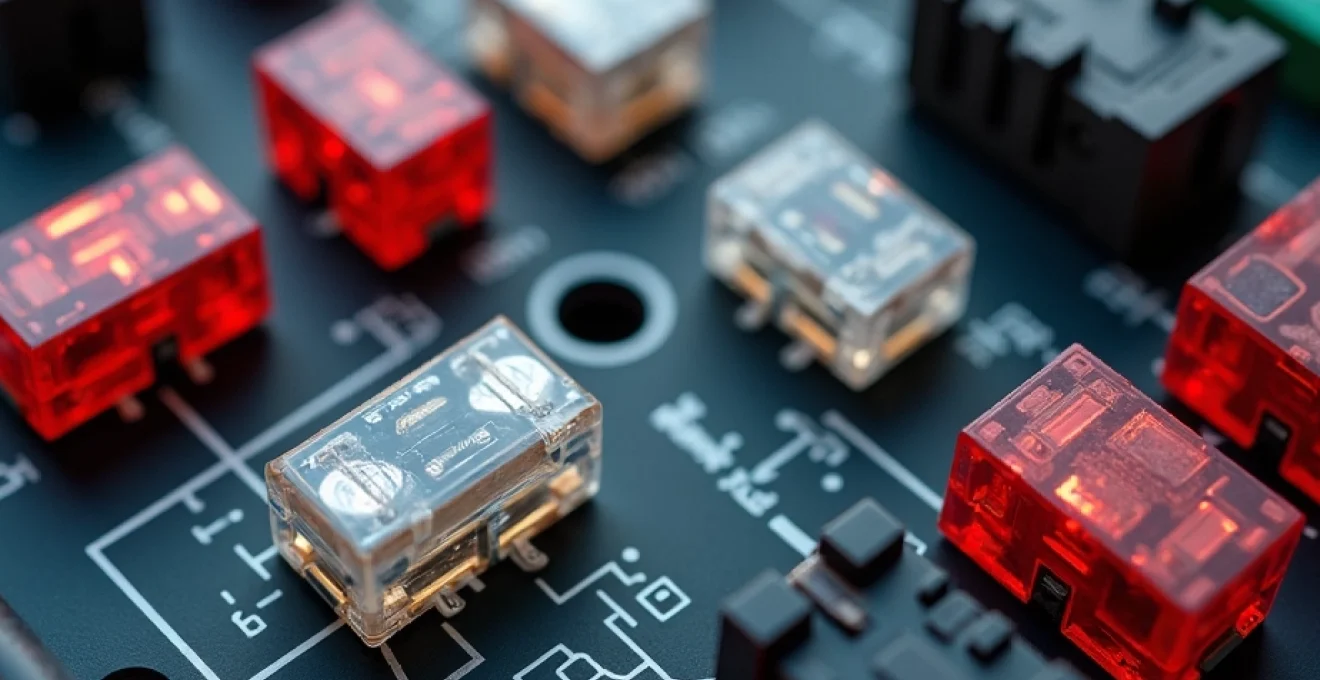
Power distribution modules (PDMs) and junction boxes serve as central hubs for a vehicle’s electrical system. These components house fuses, relays, and sometimes even small computers that manage power distribution throughout the vehicle. By centralizing these functions, manufacturers can improve reliability and simplify troubleshooting and maintenance procedures.
Modern PDMs often incorporate smart fusing technology, which allows for more precise control over circuit protection. These intelligent systems can monitor current flow and react more quickly to potential overloads, enhancing safety and reducing the risk of electrical fires.
Insulation materials: PVC vs. cross-linked polyethylene
The choice of insulation material for automotive wiring is crucial for long-term reliability and safety. Traditionally, polyvinyl chloride (PVC) has been widely used due to its low cost and good electrical properties. However, cross-linked polyethylene (XLPE) is becoming increasingly popular in automotive applications.
XLPE offers several advantages over PVC:
- Higher temperature resistance, allowing for use in more demanding environments
- Better resistance to chemical degradation, enhancing longevity
- Improved mechanical strength, reducing the risk of insulation damage
- Lower environmental impact, as XLPE does not contain chlorine
The choice between PVC and XLPE often depends on the specific application within the vehicle, with XLPE typically reserved for more critical or high-temperature areas.
Automotive fuse types and ratings
Fuses are the unsung heroes of automotive electrical systems, protecting sensitive components from potentially damaging overcurrents. Understanding the various types of fuses and their ratings is essential for maintaining and troubleshooting your vehicle’s electrical system.
Blade fuses: ATO, MINI, and MAXI variants
Blade fuses are the most common type found in modern vehicles. They are characterized by their flat, blade-like design and color-coded plastic housing. The three main variants of blade fuses are:
- ATO (regular): The standard size used in most automotive applications
- MINI: A smaller version, often used in compact or space-constrained applications
- MAXI: A larger variant designed for high-current circuits
Each type of blade fuse is available in various amperage ratings, typically ranging from 1 to 40 amps for ATO and MINI fuses, and up to 120 amps for MAXI fuses. The amperage rating is always clearly marked on the fuse body and is often color-coded for easy identification.
Cartridge fuses and High-Current applications
For circuits that require protection at higher current levels, cartridge fuses are often employed. These cylindrical fuses are typically found in the engine compartment or near the battery and can handle currents up to several hundred amps. Cartridge fuses are commonly used for major power consumers like the alternator, starter motor, or high-powered audio systems.
It’s crucial to always replace a blown fuse with one of the same type and rating . Using a fuse with a higher amperage rating can lead to circuit overload and potential fire hazards, while a lower-rated fuse may result in nuisance tripping.
Fusible links and their role in circuit protection
Fusible links are a specialized type of circuit protection device commonly used in automotive electrical systems. Unlike standard fuses, fusible links are actually short sections of wire designed to melt and break the circuit in case of a severe overcurrent situation. They are typically used to protect major power distribution points and are often found near the battery or starter motor.
One key advantage of fusible links is their ability to handle brief current spikes without failing, making them ideal for protecting circuits that experience momentary high-current draws, such as during engine starting. However, when a fusible link does fail, it usually requires replacement of an entire wire section, which can be more complex than simply swapping out a standard fuse.
Time-delay vs. Fast-Acting fuses in automotive circuits
The choice between time-delay and fast-acting fuses depends on the specific requirements of the circuit being protected. Fast-acting fuses respond quickly to overcurrents, making them suitable for protecting sensitive electronic components. Time-delay fuses, on the other hand, can withstand short-duration current spikes without blowing, making them ideal for circuits with high inrush currents, such as motors or capacitive loads.
In automotive applications, you’ll find a mix of both types. For example, fast-acting fuses might be used to protect delicate electronic control modules, while time-delay fuses could be employed in circuits powering electric motors like power windows or seat adjusters.
Fuse box locations and accessibility
Modern vehicles typically have multiple fuse boxes, also known as fuse panels or power distribution centers. These are strategically located throughout the vehicle to provide protection and easy access for maintenance. Common locations include:
- Under the hood: Often houses fuses for major engine and powertrain components
- Under the dashboard: Protects interior electrical systems and accessories
- In the trunk or cargo area: Sometimes used for rear electrical components or batteries in hybrid vehicles
The location of fuse boxes can vary significantly between vehicle makes and models. It’s always best to consult your owner’s manual for the exact locations in your specific vehicle. Many manufacturers also provide a fuse diagram inside the fuse box cover, detailing the function and amperage rating of each fuse.
Accessibility is a key consideration in fuse box design. While some fuse boxes are easily reached and opened without tools, others may require the removal of panels or covers. When designing or modifying electrical systems, it’s important to consider fuse accessibility for future maintenance and troubleshooting.
Diagnosing electrical faults: beyond blown fuses
While a blown fuse is often the first sign of an electrical problem, it’s rarely the root cause. Effective electrical fault diagnosis requires a systematic approach and the right tools. Let’s explore some advanced diagnostic techniques and common issues that go beyond simple fuse replacement.
Using digital multimeters for circuit testing
A digital multimeter is an indispensable tool for automotive electrical diagnostics. It allows you to measure voltage, current, and resistance in various parts of the electrical system. When diagnosing fuse-related issues, a multimeter can help you:
- Check for voltage on both sides of a fuse to confirm if it’s blown
- Measure the current draw of a circuit to identify overloads
- Test for continuity in wires and components to find breaks or short circuits
When using a multimeter, always ensure you’re using the correct settings and probes for the type of measurement you’re taking. Incorrect use can lead to inaccurate readings or even damage to the meter or vehicle components.
OBD-II diagnostics for electrical system issues
The On-Board Diagnostics II (OBD-II) system, standard in all vehicles sold in many countries since the mid-1990s, provides valuable insight into a vehicle’s electrical and electronic systems. OBD-II scanners can read diagnostic trouble codes (DTCs) that may indicate electrical faults, even before they cause noticeable symptoms or blow fuses.
Advanced OBD-II tools can also provide real-time data from various sensors and control modules, allowing for more in-depth diagnosis of intermittent or complex electrical issues. This can be particularly useful when dealing with problems in modern vehicles with sophisticated electronic systems.
Common causes of repetitive fuse failure
If you find yourself repeatedly replacing the same fuse, it’s a clear sign of an underlying issue that needs addressing. Some common causes of repetitive fuse failure include:
- Short circuits caused by damaged wiring or faulty components
- Overloaded circuits due to aftermarket accessories or modifications
- Worn-out or sticking relays that cause excessive current draw
- Water ingress leading to corrosion and short circuits
Identifying the root cause often requires careful inspection of the affected circuit, including tracing wires, checking connections, and testing components. In some cases, specialized tools like thermal imaging cameras can help locate hot spots in wiring that may indicate impending failures.
Upgrading and modifying vehicle electrical systems
As automotive technology advances and owners seek to personalize their vehicles, upgrading and modifying electrical systems has become increasingly common. Whether you’re adding high-powered audio equipment, auxiliary lighting, or advanced electronic accessories, it’s crucial to approach these modifications with a solid understanding of electrical principles and best practices.
Calculating wire gauge requirements for aftermarket accessories
One of the most critical aspects of electrical system modification is selecting the appropriate wire gauge for new circuits. Using wire that’s too thin can lead to voltage drop, overheating, and potential fire hazards. The required wire gauge depends on several factors:
- The maximum current draw of the device
- The length of the wire run
- The acceptable voltage drop (typically no more than 3-5%)
To calculate the correct wire gauge, you can use specialized charts or online calculators that take these factors into account. Always err on the side of caution by selecting a wire gauge that can handle more current than your calculations suggest.
Relay integration for High-Current devices
When adding high-current devices to your vehicle’s electrical system, it’s often necessary to incorporate relays. Relays allow a low-current control signal to switch a high-current circuit, protecting switches and wiring from excessive loads. This is particularly important for accessories like auxiliary lighting, electric fans, or power inverters.
Proper relay selection and installation involve considerations such as:
- The current rating of the relay (ensure it exceeds the maximum load)
- The coil voltage (typically 12V for most automotive applications)
- Appropriate mounting location (protected from heat and moisture)
- Correct wiring, including fuse protection for both the control and load circuits
Implementing secondary fuse panels for custom installations
For extensive electrical modifications or when adding multiple accessories, installing a secondary fuse panel can be a smart solution. This approach offers several advantages:
- Keeps aftermarket circuits separate from the vehicle’s original wiring
- Allows for easier troubleshooting and maintenance of added components
- Provides a central location for fuses and relays associated with modifications
- Can help prevent overloading of the vehicle’s primary fuse box
When installing a secondary fuse panel, it’s crucial to source power directly from the battery through an appropriately sized main fuse or circuit breaker. The panel should be mounted in a dry, accessible location, and all wiring should be properly secured and protected from chafing or heat damage.
As you embark on electrical system upgrades, remember that proper planning and execution are key to ensuring safety and reliability. Always consult vehicle-specific wiring diagrams and, when in doubt, seek the advice of a professional automotive electrician. By approaching modifications with care and knowledge, you can enhance your vehicle’s capabilities while maintaining the integrity of its electrical system.